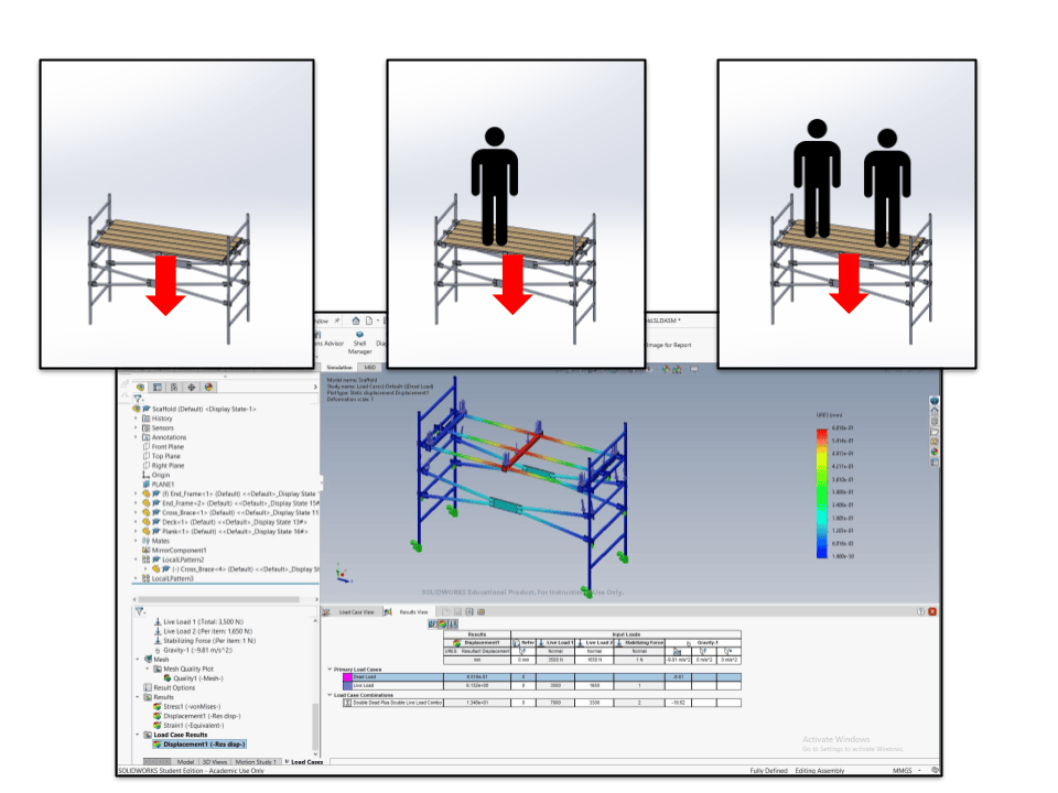
The load case manager is a feature within SolidWorks Simulation used to analyze the total structural impact when a design is subjected to multiple forces at once. It helps engineers efficiently evaluate the effects of various loading conditions simultaneously through the following functions:
- It enables the mixing of different force types, such as permanent (dead) loads like gravity and temporary (live) loads like people or objects on the structure, into new configurations.
- Simple equations are used to conveniently define and combine these load cases.
- This capability allows for the direct analysis of the total, combined effect of multiple loading conditions on the design’s structural integrity.
Scaffolding assembly
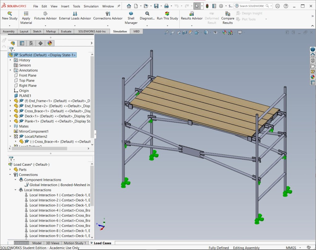
Foundation: The structural model is ready, with basic supports and Local Interactions (contacts for planks, hooks) and Global Interactions (bonded for welds) defined.
Mesh plot
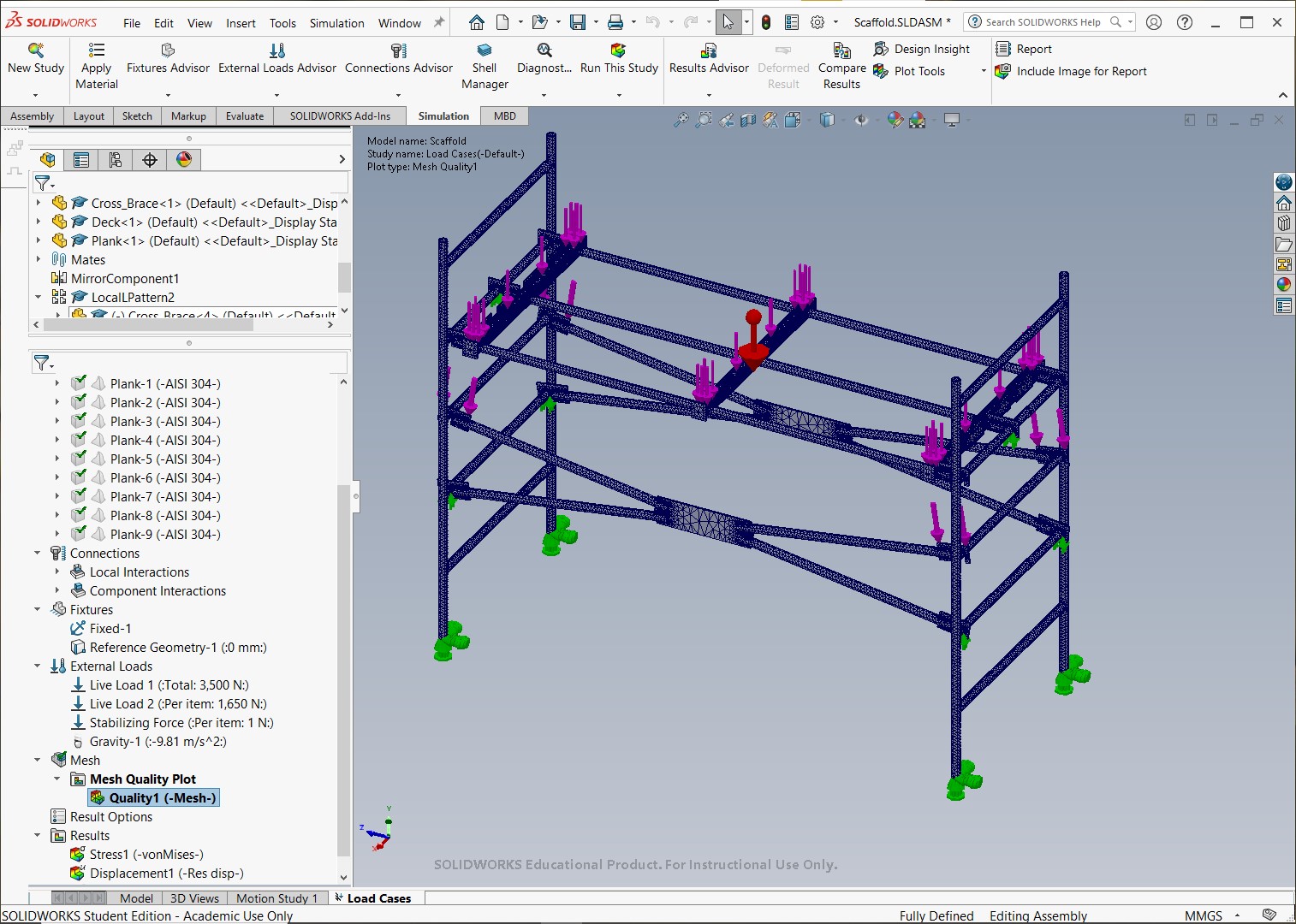
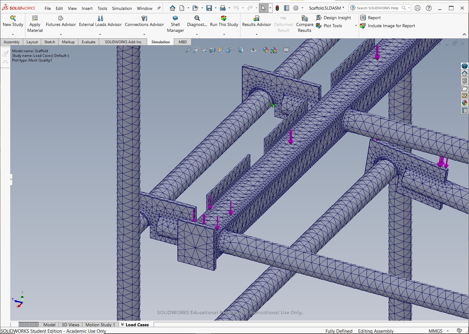
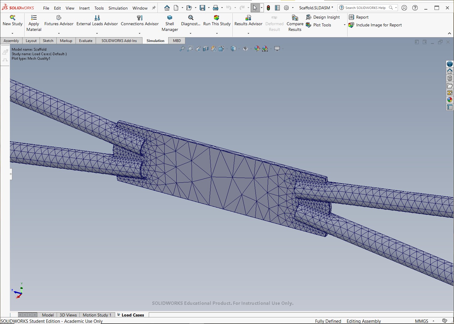
Mesh plot of the scaffold structure with primary loads applied. The arrows indicate the location of all defined primary load xases (Live Load 1, Live Load 2, and Gravity).
Input validation: This confirms the model has been meshed and shows the inputs (loads and fixtures) that are used as the base for the load case manager combination. The specific load values are visible in the feature tree.
Stress plot
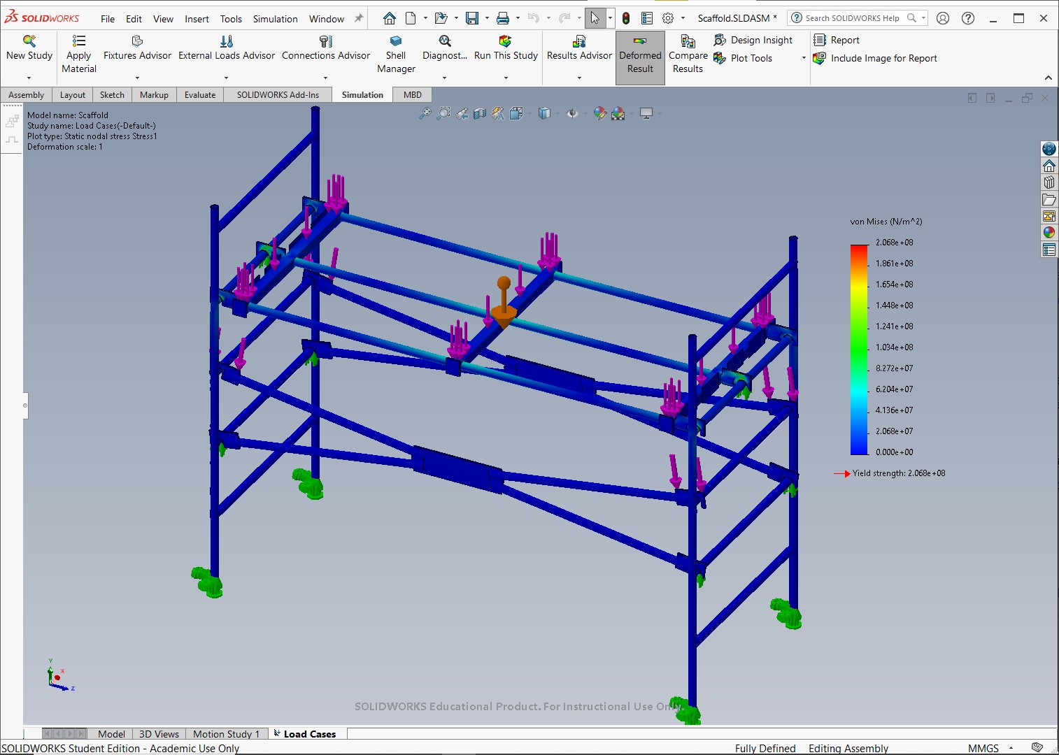
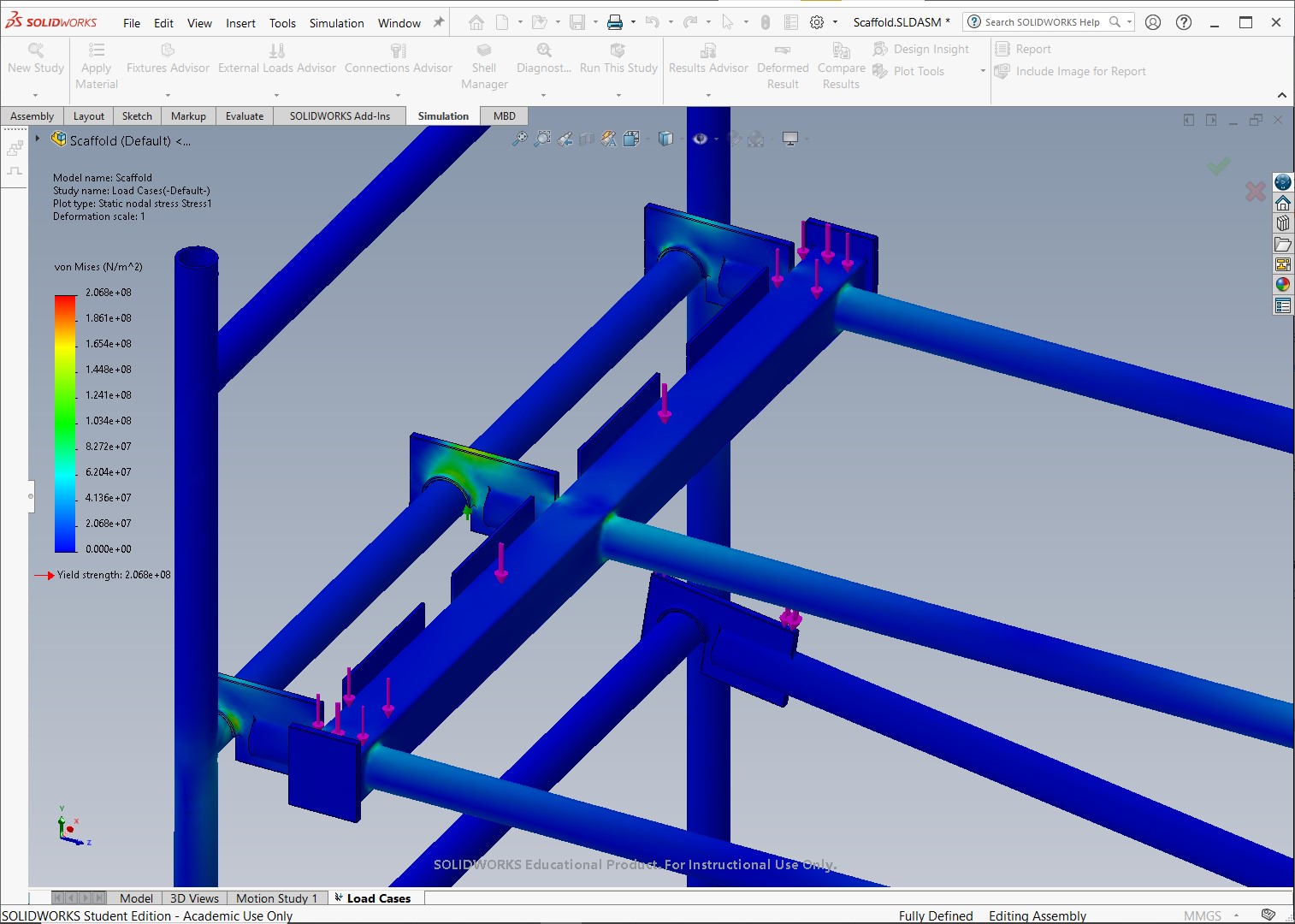
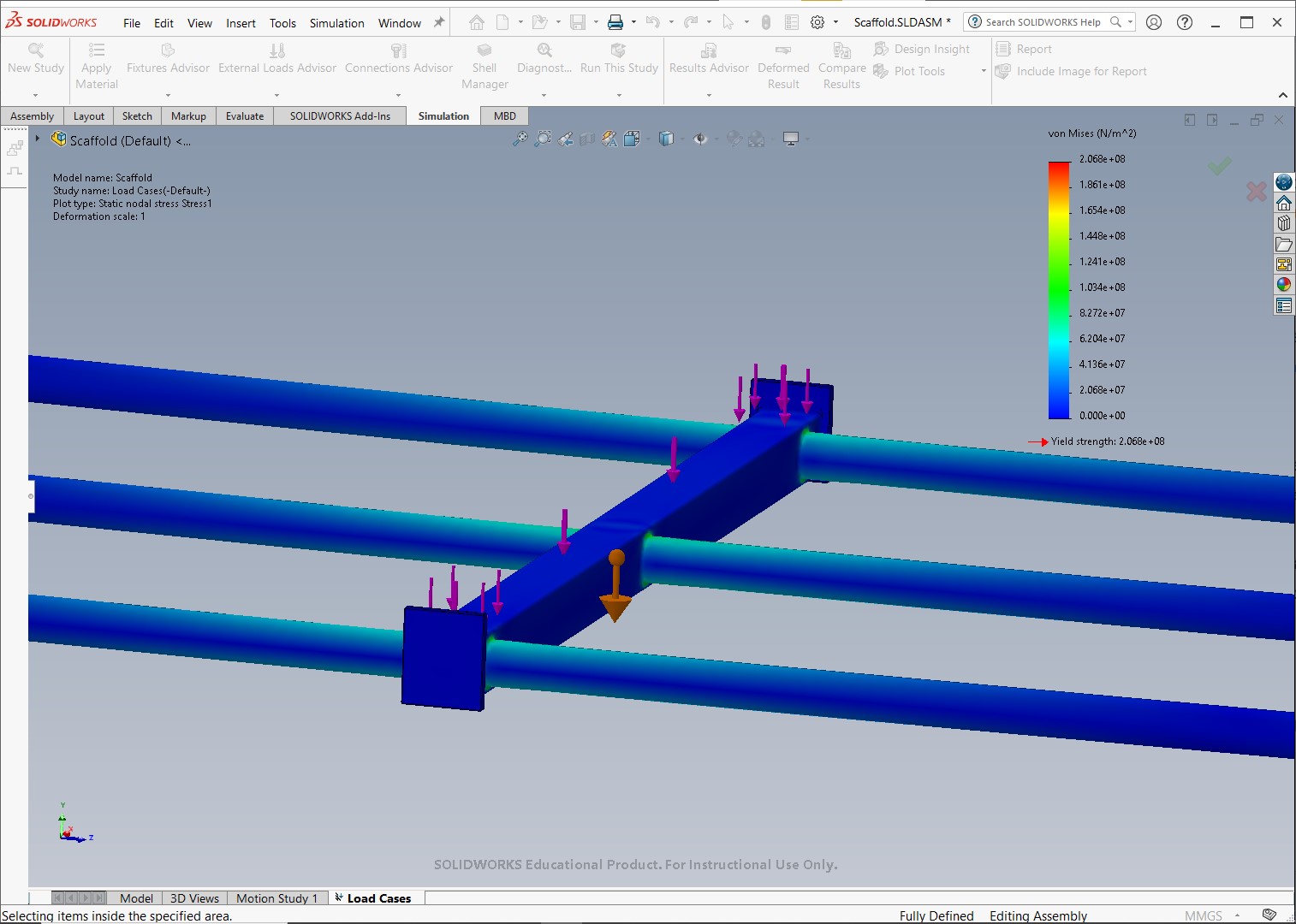
Von Mises stress plot (capped at the yield stress of 206.8 MPa) showing the initial combined stress baseline of all active primary loads in the static study
Initial result (stress plot): This is the default stress result from the static study (all loads at a 1.0 factor), serving as the unfactored stress baseline before the load case manager is used to define and evaluate custom load factor combinations.
Displacement plot
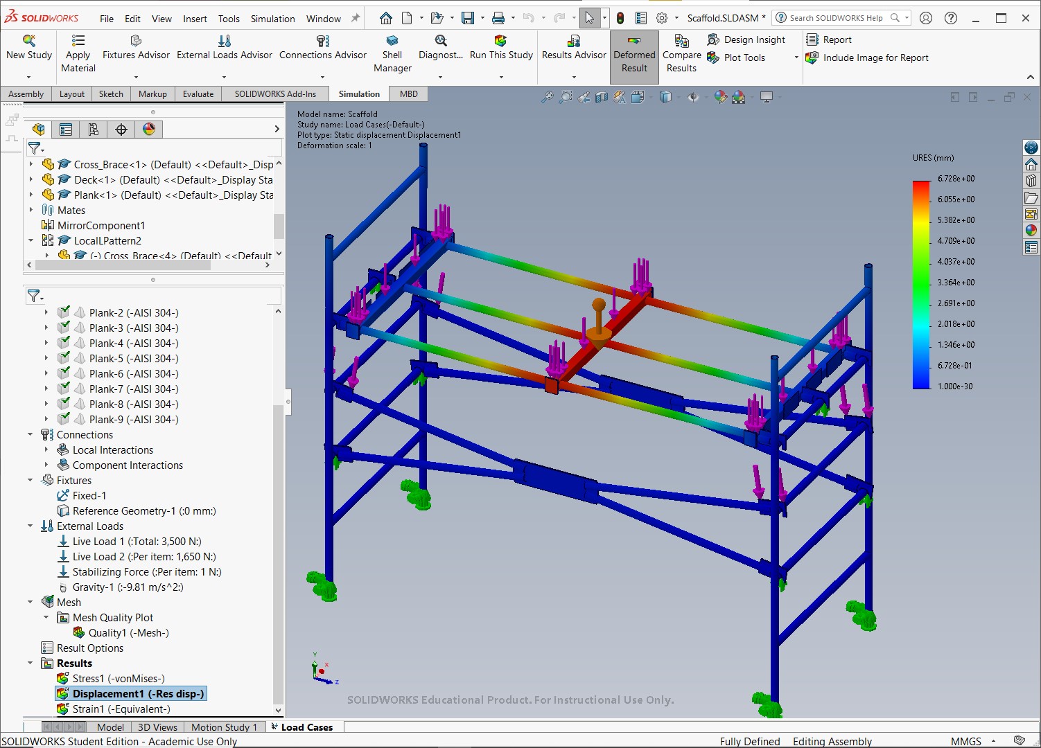
Initial result (displacement plot): Shows the total movement (resultant displacement) from the static study (all loads at a 1.0 factor). This provides the unfactored displacement baseline before the load case manager is used to define and evaluate custom load factor combinations.
Load case manager
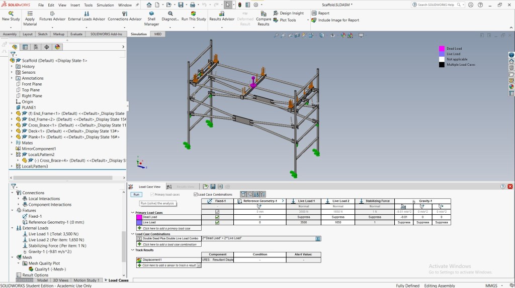
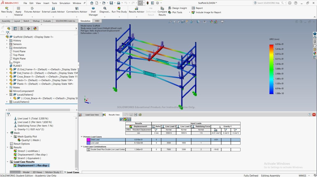
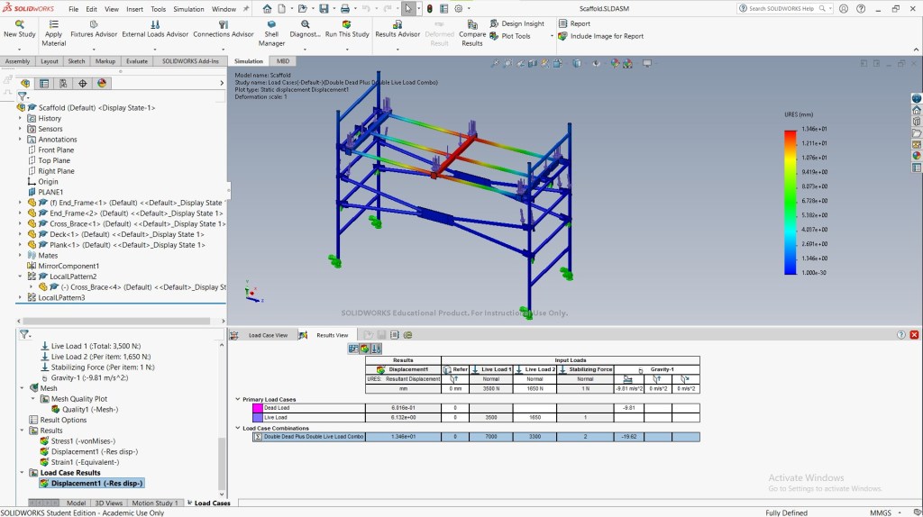
The load case manager is a convenient tool for comparing the effects of individual or combined loads on a structure. It eliminates the need to create a new study for each scenario.
In this example, we defined a load case that combines existing loads using a formula equal to twice the dead load plus twice the live load.
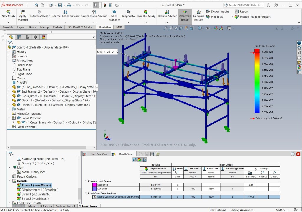
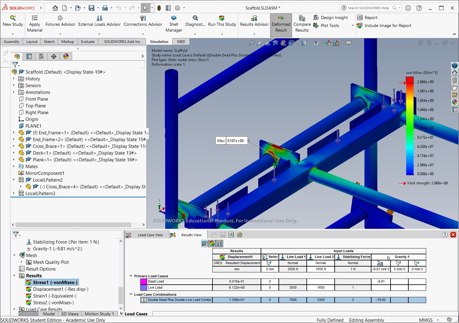
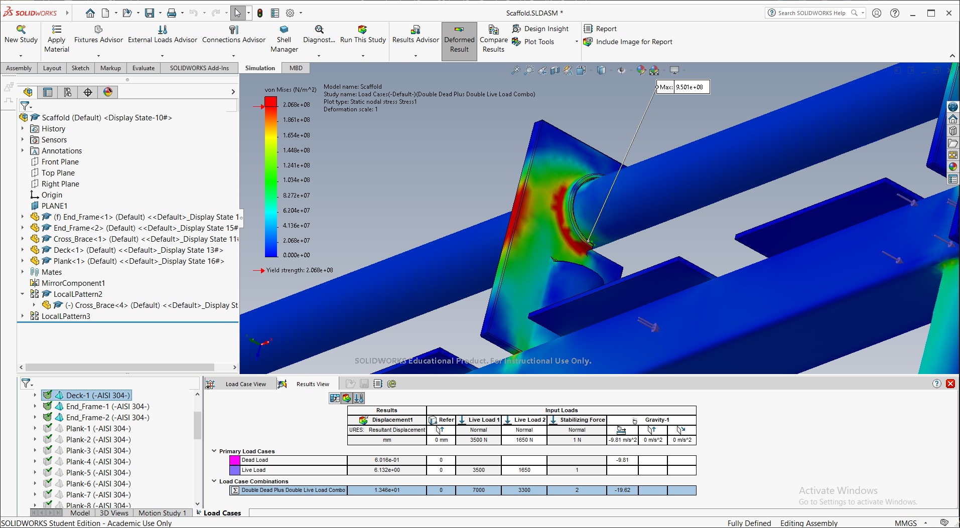
A closer view of the peak stress region shows that the support bracket connecting the deck frame experiences excessive stress and will likely require a redesign.
Source
- MySolidWorks Training
- Learning Path: SW Simulations
This content (including the analysis setup, simulation execution, and all resulting visual content—screenshots and videos) was individually performed and generated by me in SolidWorks Simulation, utilizing a combination of custom and existing parts provided by SolidWorks as guided by the MySolidWorks Training curriculum.

