Design process
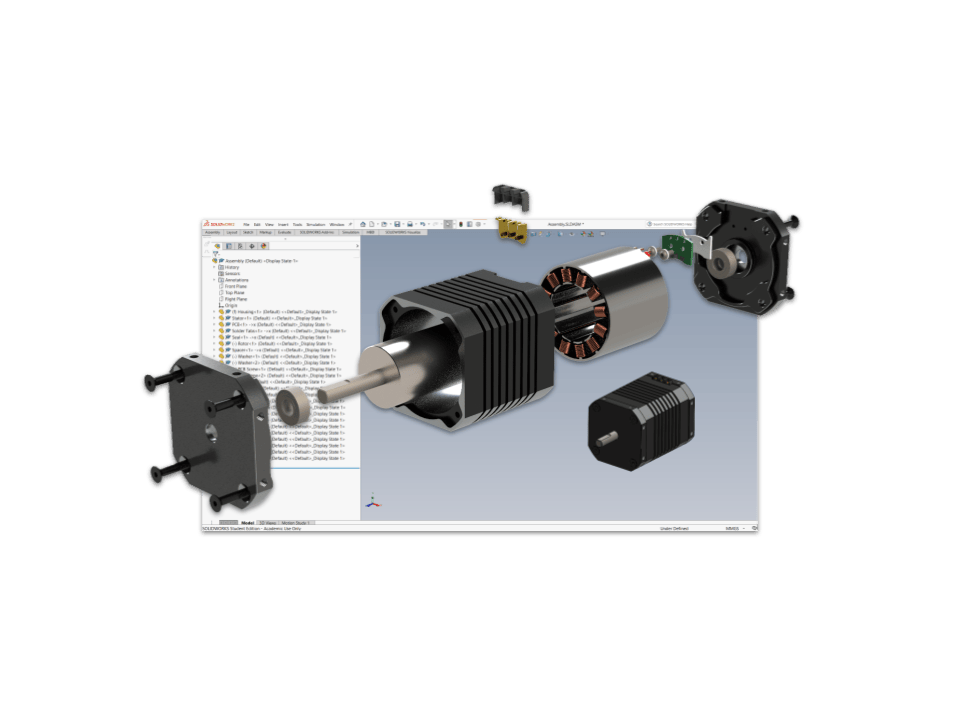
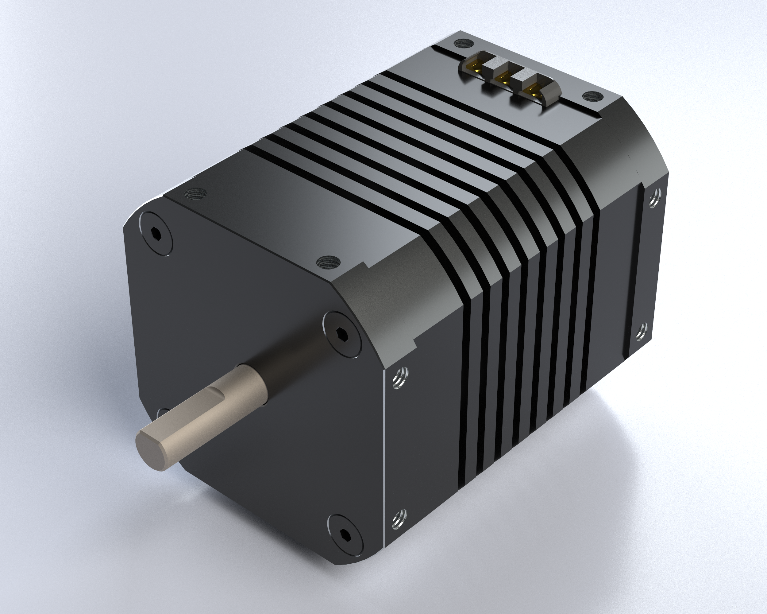
This project is a conceptual CAD design exercise created as the final assignment for my ENGE 151 class. I selected a brushless inrunner electric motor as my assembly and focused on modeling it as realistically and as manufacturably as possible, and with attention to mechatronic principles. The design includes detailed internal architecture such as stator windings, cable routing, and Hall sensor integration—to showcase both mechanical accuracy and thoughtful engineering intent.
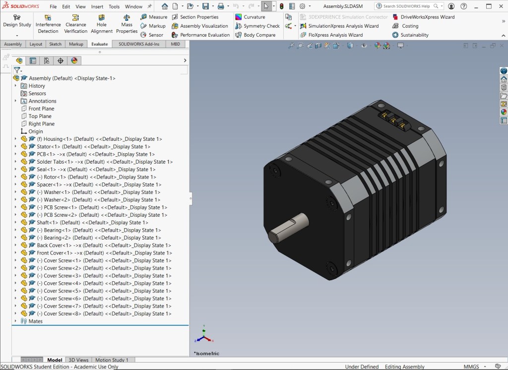
To build everything from scratch, I looked at real-world motors and common design practices to get a sense of typical dimensions, proportions, hardware conventions, and wiring considerations. There was no reference model or drawing to copy; instead, I used real examples as inspiration while determining my own dimensions and design logic—much like how engineers look at existing products to create new ones.
I designed many of the components directly within the assembly to ensure proper fit, maintain alignment, and avoid interferences. It was also simply more efficient—working on top of neighboring parts made it easier to visualize clearances and refine geometry without constantly switching in and out of separate part files.
Technical drawings
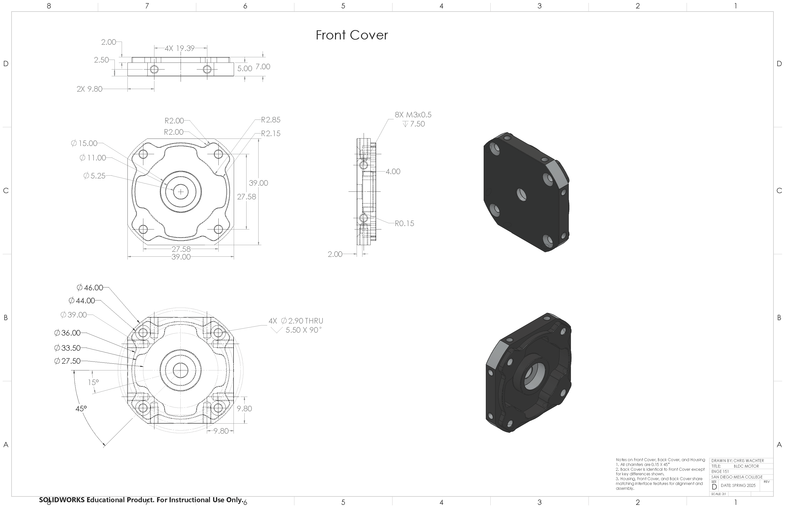
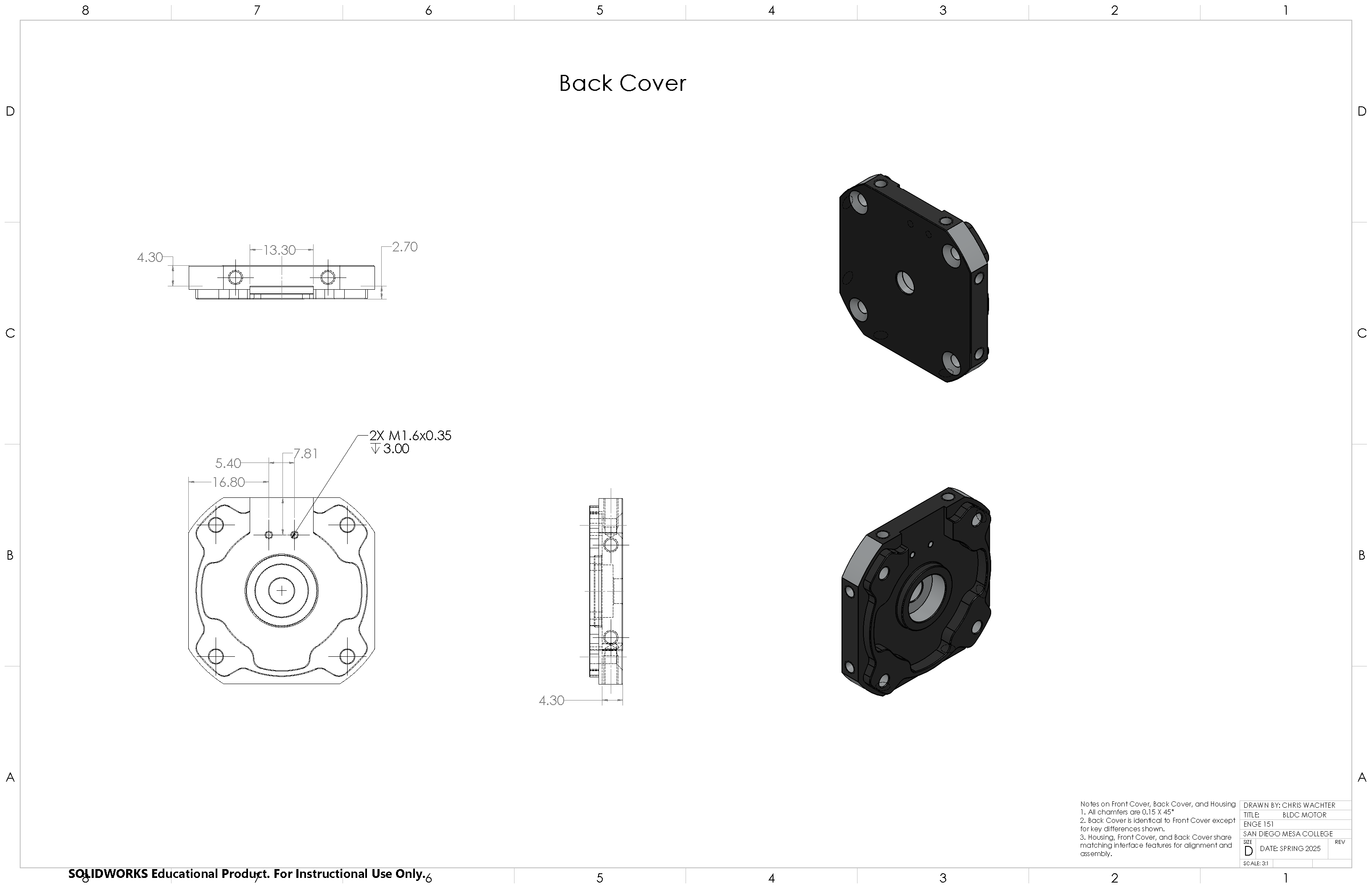
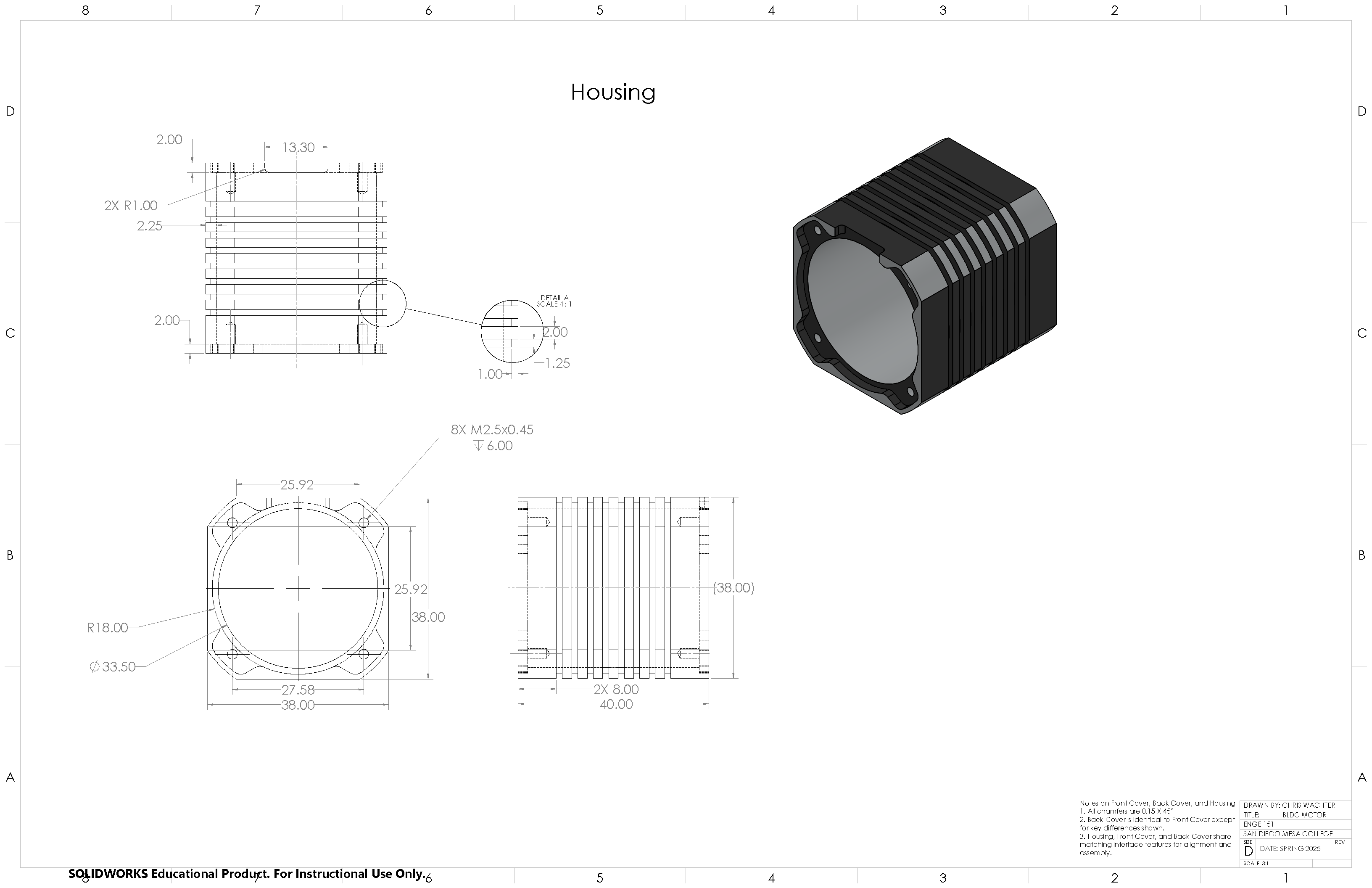
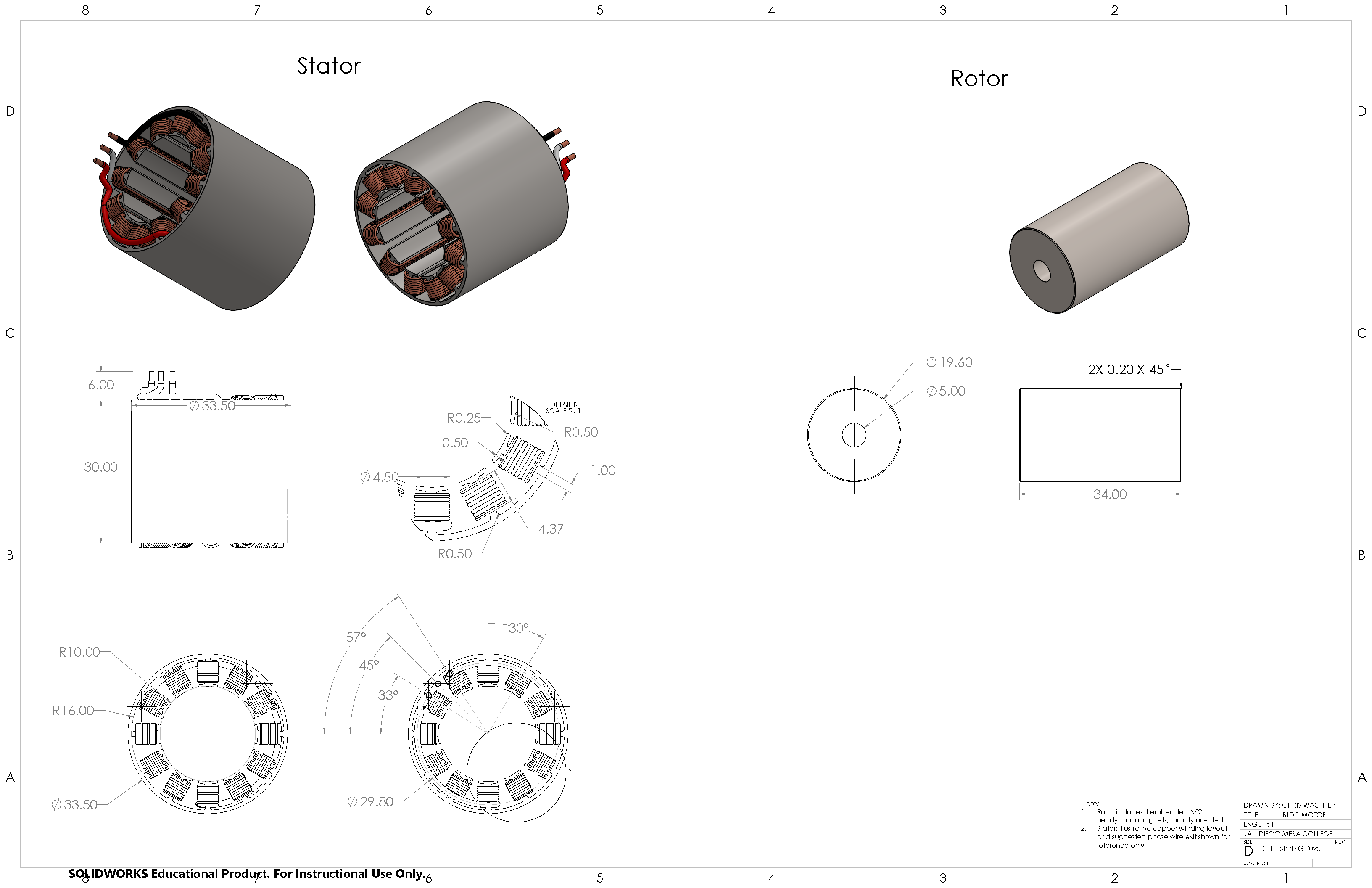
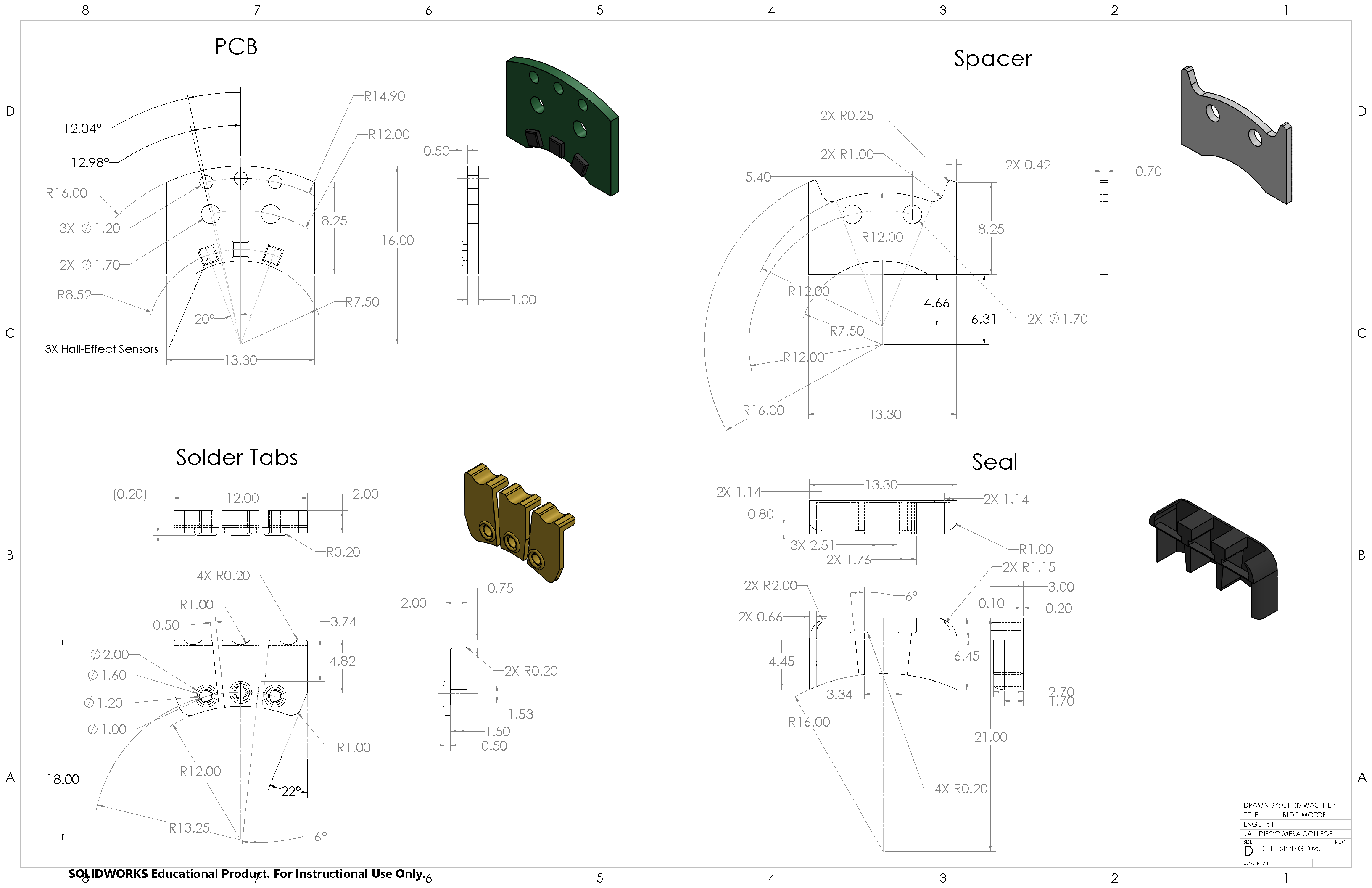
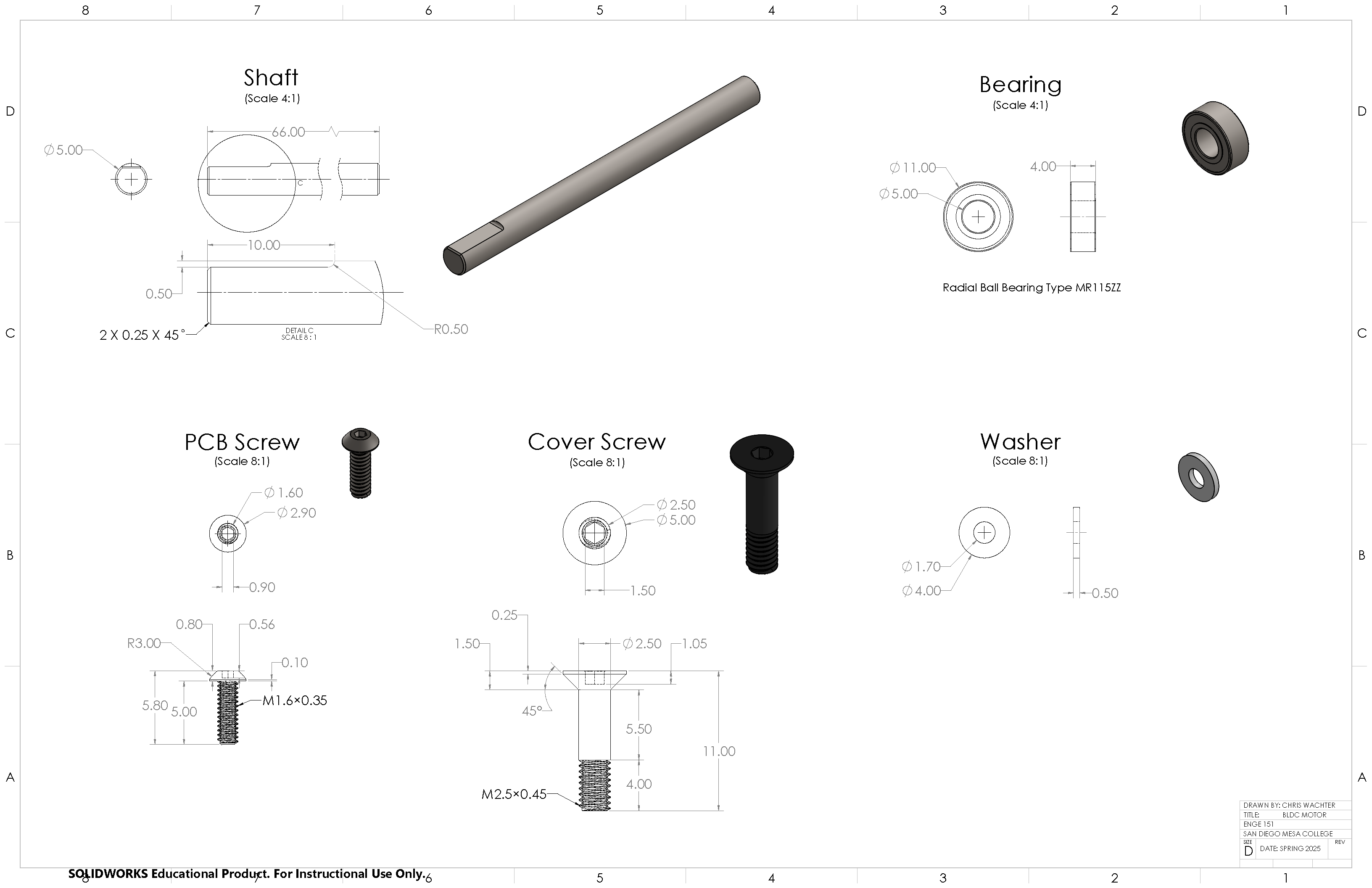
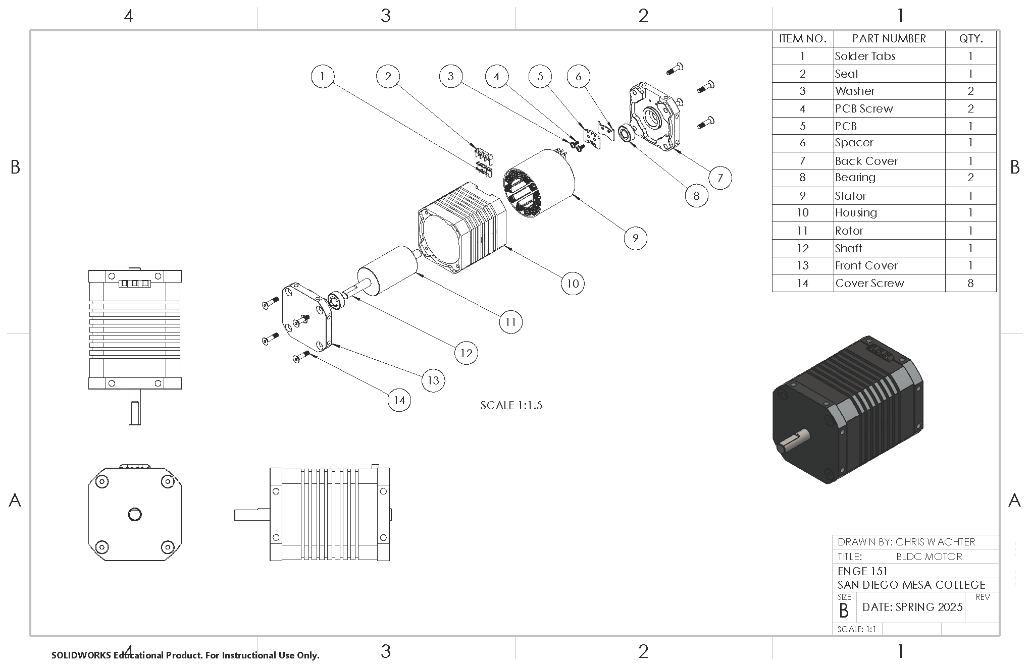
Click on images to expand

